

The Safe State for Circulo Safe Motion is
- STO/SBC active
- All digital outputs in state Low
- Safe speed valid flag, safe position valid flag, safe analog value valid flag set to not valid
- On FsoE a FailSafeData command will be send
For safety systems, it is important to distinguish between failures, errors and violations:
Failure:
A failure is a serious fault in SMM. If a failure occurs, SMM will go into a safe state and will usually not leave this state. The fieldbus communication might be deactivated. A power cycle might help to reset. Those Failures are reported with SmmFInxx.
Example: failure of a DCDC regulator inside the SMM or a memory test failed.
Error:
This could be a fault in configuration or application. Errors can be reset by Error Acknowledge. SMM will go into a safe state. Those Errors are reported with SmmFIOxx
Example: Safe Digital input state is different for inputs A/B.
Violation:
A violation happens when one of the monitoring safety functions is activated and the non-safe part violates it. The reaction to violation can be chosen during the configuration. As those violations are a regular behavior, there is no fault message shown. You can find the last violations in the log of the drive.
Negative logic
The safety functions use a negative logic: 1
Means that the safety function is disabled/not triggered, and 0 means that the safety function will be triggered. This way, a cable fault will not cause a dangerous situation, as the drive enters a safe state when the voltage is not applied anymore.
The safety functions use a negative logic: 1
Means that the safety function is disabled/not triggered, and 0 means that the safety function will be triggered. This way, a cable fault will not cause a dangerous situation, as the drive enters a safe state when the voltage is not applied anymore.
Restart Acknowledge
Restart Acknowledge
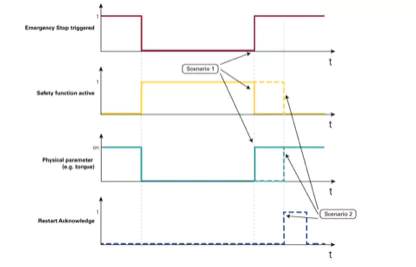
Safety conditions can be lifted via a Restart Acknowledge signal (Scenario 2 in the image below). Otherwise, the system is free to continue its work once the violation has been removed (Scenario 1 in the image below).
If the Restart Acknowledge is required can be configured individually on stopping functions STO and SOS.
- Restart acknowledge not enabled: 0x 00
- Restart acknowledge enabled: 0x FF
Acknowledge via drive
With the safety parameter “Acknowledge via drive” it can be configured if the Restart Acknowledge can be done as well in a “non safe” way by the drive. Whether this is allowed or not is depending on the overall system safety concept.
ATTENTION: Restart Acknowledge is required at some point in the implementation. If it is not configured in the drive, it has to be implemented on the safety master side. If no Restart Acknowledge signal is used, the status can oscillate between restart and stop continuously.
Standalone Mode
SMM can work without FSoE. In this case, the safety functions shall be mapped to Safe IOs. Safety Functions are activated when both input signals of a safe digital input are logical zero. If only one input goes to zero, SMM assumes there is a cabling fault and it goes to safe state. For stopping functions, the timing starts with the negative slope. For Monitoring functions, Monitoring starts with the negative slope.
SMM can work without FSoE. In this case, the safety functions shall be mapped to Safe IOs. Safety Functions are activated when both input signals of a safe digital input are logical zero. If only one input goes to zero, SMM assumes there is a cabling fault and it goes to safe state. For stopping functions, the timing starts with the negative slope. For Monitoring functions, Monitoring starts with the negative slope.
Priority of Safety Functions
All enabled safety functions are executed in parallel. Any triggered STO(/SBC) will be with highest priority.
All enabled safety functions are executed in parallel. Any triggered STO(/SBC) will be with highest priority.
Fieldbus enabled (FSoE)
Fieldbus enabled (FSoE)
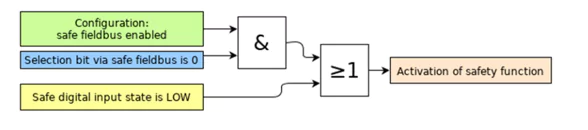
If safe fieldbus (FSoE) is enabled, the safety functions can be enabled via FSoE and IOs. Activation by FSoE and safe digital IO can be done in parallel.
The objects can be changed via FSoE.
The minimum FSoE cycle time shall be 6 ms, this does not change the cycle time of EtherCAT. This only means that the FSoE Status word is updated every 6 ms.
The internal cycle time of the SMM is 1 ms. SMM is not synchronized with the distributed clock of EtherCAT (DC Clock). This means the EtherCAT cycle time of 1 ms and the SMM can drift away from each other. Therefore, the uncertainty of the sample time of the safe data of the SMM is 1 ms. This uncertainty can be a problem for the FSoE master when calculating the kinematics based on the safe position from multiple drives. High jumps in overall velocity can be expected.
There are two suggestions for enhancing the performance:
- The FSoE Master uses the non-safe data for the calculation of the Kinematics and only uses safe data for verification.
- The FSoE Master uses safe speed data to interpolate the speed calculated from the safe position.
Using Position and Speed based monitoring functions
Configuration of Encoders
To use position or speed based safety functions, the configuration of encoders for reading position information is required.
The encoders have to be configured in the non-safe standard configuration in the drive and as well in the safety parameters. Both configurations have to match.
Reaction to violation of monitoring functions
When SLS or SMS is configured, the reaction to the safety function has to be set as well. The reaction can be:
- STO (+ SBC)
- SS1
- SS2 + SOS
In order to use SS1 or SS2 as a reaction for violation, they also need to be configured.
Reaction to violation of stopping functions
Violation reaction to stopping functions (SS1, SS2 and SOS) is always STO + SBC (if there is a safe brake). In order to protect a fragile pin brake, a delay between STO and SBC can be set.
Safe state status
The Safety Statusword indicates the current state of safety functions, including the safe in- and outputs. The object 0x2611 Safety State Diagnostics shows the state of the safety. 0 value means no release for brake and motor torque; find more informations in “Safe Data via FSoE”).
In regular function, both states are in the same state (0 or 1). If not, there is a hardware fault on SMM. One state <> 0 will already disable drive and brake. If safety releases movement, the non-safe drive control can additionally switch off the drive and engage the brake (e.g. a regular disable of drive on stand still). But without a safety release, the drive can not be switched on.