

Device Profile for Motion Drives.
EtherCA
EtherCAT is defined by the EtherCAT user group in the IEC-Standard 61158 and defines the bus system and how the drive slave communicates with a master on the physical and basic communication levels.
CANopen
CANopen is standardized by CiA and the CiA 301 describes the CANopen application layer and the communication profile.
This describes how to transfer content between a master and a slave and how to realize the real time requirements.
CoE
CoE specifies how the CANopen protocol is used in the EtherCAT environment.
CiA 402
CiA 402 is the device profile for drives and motion control applications. CiA 402 defines how drives communicate with the masters:
The object number designates where to find, or send, the required information and all basic functionality; for example, how to switch on a drive, how to recover faults, drive specific state machines.
Complying with CiA 402 makes drives interchangeable among different manufacturers as all drives work similarly and have the same basic data on the same address. Manufacturer specific areas define how to handle special features.
Masters are based on these standards and offer an abstraction layer; therefore, only minor knowledge about the standards is required. The system offers an interface (usually graphical), so that the system can be configured as needed. The user need not be concerned about protocols, such as starting up the communication, fault and recovery procedures, PDO mapping, and communication supervision, because this is handled by the master. Usually, process values can be set by the user directly through the API of a master software without having to worry about the details.
Nevertheless, having basic knowledge of the basic principles will help to establish the connection with these masters, bug fixing and fault diagnosis.
If a commercial master is not used and the interface to a SOMANET drive is manually implemented or the system is realized with the use of free basic solutions, such as SOEM, a deep knowledge of the standard is required
Ethernet for Control Automation Technology
EtherCAT (Ethernet for Control Automation Technology) is an Ethernet-based fieldbus system. The protocol is standardized in IEC 61158 and is suitable for both hard and soft real-time computing requirements in automation technology.
EtherCAT can handle difficult real time requirements, and the built-in synchronization mechanisms allow synchronized movement of multiple drives.
An EtherCAT network consists of an EtherCAT master and one or more EtherCAT slaves. SOMANET servo drive is an EtherCAT slave. To operate it, an EtherCAT master is required.
CANopen over EtherCAT
CANopen is a communication protocol and device profile specification for embedded systems used in automation. The CANopen over EtherCAT protocol (CoE), which is used by all SOMANET servo drives, enables the complete CANopen profile family to be utilized via EtherCAT to ensure both high functionality and good communication performance.
CANopen is maintained by the CiA (CAN in Automation User Group) and is standardized by the European Norm EN 50325-4.
The CANopen protocol is not only restricted to physical CAN networks, but can also be used on other field bus systems such as EtherCAT or PowerLink.
Sufficient knowledge of CANopen concepts is also very important for correctly controlling Synapticon drives. The basic CANopen application layer and communication profile is specified in CiA 301. Based on this, the CANopen device profile for drives and motion control, which is known as CiA 402 whose 2.0 version is standardized as IEC 61800-7-201 from 2015, is released and conformed to by many servo drives including ours. It is recommended that users read these CAN in Automation standards before controlling SOMANET drives using a general EtherCAT master, while some essential concepts related to applications are introduced below as a quick guide.
CANopen basic Principles
TAll operable data in a CANopen device, including communication data and application data, is stored in an object dictionary. Each data can be accessed with a 16-bit index and an optional 8-bit subindex. For example, the measurement “Velocity actual value” is stored in 0x606C, and the configuration “Brake output voltage” is stored in 0x2004:10. A complete object dictionary of SOMANET servo drives with firmware v5.0 can be found here.
Each CiA compliant device has a specific ESI file (EtherCAT Slave Information). Besides other device specific information, the ESI file contains the object dictionary.
To read/write data in a CANopen device, two methods as shown below are generally used.
Service Data Objects
SDO (Service Data Objects) can provide direct access to reading/writing any object entries in an object dictionary. However, this is performed on demand and not cyclically, so it is mainly used for changing configurations, reading error codes or other actions on demand.
All objects can be read, but only some can be written as well (RO / read only <-> RW read write).
Process Data Objects
PDO (Process Data Objects) can provide real-time data transfer in a cyclic manner; it is mainly used to transfer time-sensitive cyclical application data such as controlword/statusword, target/actual velocity etc. There are two kinds of PDOs: Transmit PDO (TPDO) and Receive PDO (RPDO), which provide slave-to-master and master-to-slave data transfer respectively. To configure a PDO, two objects in the object dictionary must be configured by means of SDO. The first is the PDO parameter and the second PDO mapping. The PDO parameter describes the communication capabilities of the PDO while PDO mapping determines which object shall be mapped to this PDO to be transferred in real-time cyclically. By default, our standard PDO configuration already covers common application data so there is no need to configure “from scratch”.
PDO (Process Data Objects) can provide real-time data transfer in a cyclic manner; it is mainly used to transfer time-sensitive cyclical application data such as controlword/statusword, target/actual velocity etc. There are two kinds of PDOs: Transmit PDO (TPDO) and Receive PDO (RPDO), which provide slave-to-master and master-to-slave data transfer respectively. To configure a PDO, two objects in the object dictionary must be configured by means of SDO. The first is the PDO parameter and the second PDO mapping. The PDO parameter describes the communication capabilities of the PDO while PDO mapping determines which object shall be mapped to this PDO to be transferred in real-time cyclically. By default, our standard PDO configuration already covers common application data so there is no need to configure “from scratch”.
CANopen Device Profile CiA 402 for drives and motion control
CANopen Device Profile CiA 402 for drives and motion control
CANopen defines profiles for specific devices as IO-modules, sensors or drives. The profile for power drives is defined in CiA 402.
CiA 402 compliant drives have the same basic functionality and can easily be interchanged, even when they have manufacturer specific objects.
In CiA 402, it is specified that the behavior of a Power Drive System (PDS) should be controlled by a Finite State Automaton (FSA). The PDS FSA has many states, and each state shall support a specific set of functions. For example, moving a motor is only possible in the state “Operation enabled”. State transitions can be triggered by writing the object “0x6040 Controlword” or internal fault signals (which transits the state to “Fault reaction active”) and the current state of the FSA can be read from the object “0x6041 Statusword”. See: Using Statusword and Controlword for a detailed description and illustration.
Power Drive System
The behavior of a Power Drive System is also determined by the activated mode of operation. The mode of operation can be selected by writing the object “0x6060 Modes of operation”. It defines how users would like to move the motor (for example, by setting the target torque/velocity/position with a self-defined trajectory in profile modes, or by updating the torque/velocity/position cyclically in cyclic synchronous modes). The aforementioned Controlword and Statusword also have some specific operation mode-specific bits to extend functionalities. Refer to this page for the definitions of all modes of operation that SOMANET supports.
The behavior of a Power Drive System is also determined by the activated mode of operation. The mode of operation can be selected by writing the object “0x6060 Modes of operation”. It defines how users would like to move the motor (for example, by setting the target torque/velocity/position with a self-defined trajectory in profile modes, or by updating the torque/velocity/position cyclically in cyclic synchronous modes). The aforementioned Controlword and Statusword also have some specific operation mode-specific bits to extend functionalities. Refer to this page for the definitions of all modes of operation that SOMANET supports.
EtherCAT state machine
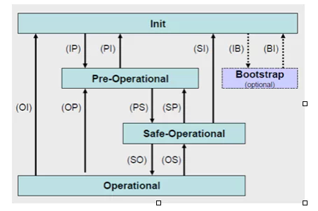
EtherCAT state machine
The figure below depicts the EtherCAT state machine and describes which communication is possible in which state.
Drive state machine
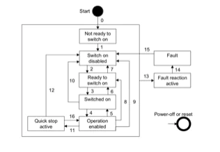
Drive state machine
The figure below specifies the drive state machine with its state transitions based on user commands and internal drive faults.
PDO-Mapping
There is a standard set of PDO that consists of input objects (TxPDO) and output objects (RxPDO) in the firmware. The set covers almost all application data that will be used in real applications, generally configuration is not necessary.
However, if there are objects that are more suitable for the application, an individual set of PDO can be created by the following procedure:
- Ensure that the desired object is PDO mappable (this can be checked in the object dictionary)
- Switch EtherCAT state to Pre-operational
- Disable PDO distribution by setting 0 to 0x1C12:00 (for RxPDO) or setting 0 to 0x1C13:00 (for TxPDO)
- Disable one of the PDO mapping objects by setting its subindex 0 to 0
- Enter the objects that should be mapped to the mapping entry subindices 1 to n
- Set subindex 0 to the number n of used entries
- Enable PDO distribution by setting 0x1C12:00 or 0x1C13:00 to their original values, by default 3 and 4 respectively
Changing the PDO mapping will not permanently be stored on the drive. The reconfiguration must be done on every new start of the drive.
Many commercial masters provide the possibility to change the PDO mapping when configuring a device. The master will then change the PDO mapping automatically after every boot-up before enabling the operational state of the drive.
Communication Frequency and DC-Clock Synchronization
The communication frequency of EtherCAT systems is determined by the master’s update rate, which is often represented as cycle time. Usually, the cycle time should be set between 250 μs and 8 ms. There are a few tips that may help to find the most appropriate cycle time based on the application and situation.
- When the cycle time is lower than 1 ms, a high performance of the hardware system is required.
- SOMANET drives have a sample time of 250 μs internally; therefore, if the master’s cycle time is set below this value, the application performance will generally not improve noticeably.
- In real-time applications, commands are sent to the slaves with a step size that depends on the master’s update rate; if the application requires fast command changes, a slow cycle time will have negative effects on control performance. If the control performance is limited by the hardware system, the control loop should be tuned relatively soft, or an FIR filter should be considered.
In EtherCAT systems, the clocks of master and slave(s) can be synchronized based on a Distributed Clock (DC) technology. This is especially important when multiple slaves are present and complex synchronous motions are required. When no distributed clock is available, the clocks on the slave and master devices will drift, and this will cause a cycle to periodically either miss a command, or complete before the command arrives at the controller. This will effectively either double the input command or see no change to the input command.